How to Configure and Maintain the IS230TBAIH3C Analog I/O Terminal Board for Optimal Performance
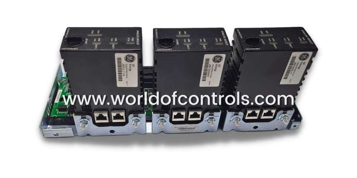
The IS230TBAIH3C is a critical component in GE's Mark VIe turbine control systems, serving as an Analog Input/Output Terminal Board that handles 10 analog inputs and 2 outputs with support for simplex or Triple Modular Redundant (TMR) configurations. This board ensures precise signal acquisition and transmission in demanding industrial environments, where reliability directly impacts turbine efficiency and safety. Mastering its configuration and maintenance minimizes downtime, prevents faults, and optimizes performance in power generation applications.
Hardware Installation
Proper installation forms the foundation for reliable operation of the IS230TBAIH3C. Begin by selecting a compatible I/O rack in the Mark VIe cabinet, mounting the board using DIN rail clips or panel screws for secure fixation. Ground the board to the rack's earth bar using at least 14 AWG wire to mitigate electromagnetic interference (EMI), a common issue in turbine control rooms with high-voltage proximity.
Connect field wiring to the two 24-position terminal blocks, accommodating wires up to #12 AWG. Tighten screws to the manufacturer's torque (typically 7 in-lbs) and route shield wires to dedicated shield terminals, twisting shields to minimize noise pickup. The board features three DC-37 pin connectors: JR1 for simplex setups linking to a single VAIC or PAIC processor, or JR1/JR2/JR3 for TMR redundancy, enabling fan-in/fan-out signal distribution across multiple controllers. After connections, perform a dry run power-up test without field devices to verify no shorts, using a multimeter across terminals.
Jumper Configuration
Jumpers on the IS230TBAIH3C dictate signal types, ranges, and isolation, making accurate setup essential to avoid signal distortion or board faults. For inputs 1-8, jumpers J1A through J8A select between current mode (4-20 mA) or voltage (±5V or ±10V); pair with J1B-J8B for common-return or floating configurations to match transducer outputs. J9A and J10A fine-tune input scaling (1 mA or 20 mA full scale), while J0 configures output channel ranges, such as 0-20 mA or 0-200 mA on one channel.
Always reference the board's silkscreen labels and GE installation diagrams during jumper placement, as incorrect settings can trigger diagnostic alarms or zero readings. In TMR mode, ensure identical jumper positions across redundant boards for consistent voting. After reconfiguration, cycle power and monitor the processor's diagnostic LEDs for faults before integrating into the control loop.
Wiring and Power Setup
Wiring must prioritize signal integrity, especially for 2-wire, 3-wire, or 4-wire RTDs, thermocouples, or transmitters connected to the IS230TBAIH3C. Terminate positive/negative signals on designated blocks, observing polarity, and limit lead lengths to keep resistance under 15Ω total to prevent voltage drops. The board supplies 24 V DC (up to 21 mA per channel, fused and short-circuit protected) for externally powered transducers, with diode-sharing in TMR for load balancing.
Outputs drive loads up to 500Ω maximum, incorporating series resistors and optional suicide relays that open on uncorrectable faults to protect downstream equipment. Implement noise suppression with ferrite beads on long runs and separate power/signal grounds. Surge protection handles transients up to 100 V, but verify compliance with site standards like NEC Class 1 Division 2. Post-wiring, conduct continuity tests and apply 28 V DC loop power to confirm 4-20 mA compliance without oscillations.
Software Integration
Seamless software integration elevates the IS230TBAIH3C from hardware to a fully monitored system asset. Use GE's ToolboxST or Proficy Machine Edition on the HMI workstation to map signals post-hardware setup. Calibrate inputs via the software's signal conditioner blocks, setting zero/span values and enabling filtering (e.g., 4-40 Hz low-pass) to reject 50/60 Hz noise.
Configure TMR median voting for outputs, where discrepancies trigger alarms and relay trips. Diagnostics poll shunt resistors for current verification and fault logging, accessible via the Mark VIe database. Test end-to-end by injecting known signals (e.g., 12 mA for 50% span) and verifying ToolboxST trends match within 0.1% accuracy. Firmware updates from GE ensure compatibility with evolving control logic.
Maintenance Procedures
Routine maintenance sustains long-term performance of the IS230TBAIH3C in harsh conditions (-30°C to +65°C operating range, 5-95% humidity non-condensing). Quarterly, de-energize the rack, visually inspect terminals for looseness, corrosion, or arc marks, and torque to spec. Clean dust from connectors with compressed air and isopropyl alcohol wipes, avoiding abrasives.
Recalibrate annually or after 10,000 hours using ToolboxST, comparing field values against precision sources. Monitor power draw (nominal 4 W at 21-56 V DC input) via the processor; spikes indicate failing components. Stock GE-approved spares, swapping boards slot-by-slot in simplex mode or synchronizing in TMR. Log all activities in the maintenance ledger for compliance with ISO 9001 or NERC standards.
Troubleshooting Tips
Quick diagnosis resolves most IS230TBAIH3C issues without full outages. No-signal faults often trace to jumper mismatches—reverify J1A-J10A against docs—or open loops; test with a 250Ω calibrator. Noise or drift points to poor shielding: re-twist drains, add MOVs across inputs, or check ground loops with a milliohmmeter (<1Ω target).
TMR discrepancies activate voting alarms; inspect diode networks and shunt calibration. Power faults (under 9 V DC) trip undervoltage protection—measure at TB1 pins. Use ToolboxST event logs for timestamps, cross-referencing with LED codes (e.g., steady red for hardware fail). If persistent, invoke GE Field Service for oscilloscope analysis of high-frequency glitches.
In summary, diligent configuration and maintenance of the IS230TBAIH3C - Analog Input/Output Terminal Board
ensure turbine controls operate at peak reliability, reducing unplanned shutdowns by up to 30% in optimized systems. Operators in power plants benefit from its robust design, but adherence to these steps is non-negotiable for safety and performance.
Check Also - IS200TBCAH1A - RTD Input Termination Module